1. "Why should we upgrade to 25G Ethernet?"
In the past years, we have observed that many Internet data centres have upgraded their server access from 10G Ethernet to 25G Ethernet. Why do people want to upgrade to 25G Ethernet?
Following information furnish a concise answer to the above mentioned question:
● Supporting high-performance businesses, involves collaborating with rapidly expanding businesses to enhance application system performance. For instance, internet applications based on AI and big data have led to a significant increase in business traffic.
● Supporting business emergencies is crucial, especially when there are sudden business crises that require full infrastructure support from the business side.
● Matching the upgrade of server performance, entails enhancing the server CPU and storage I/O performance, which in turn boosts the network throughput performance of each server. It has been observed that 10G networking is insufficient to meet the bandwidth requirements.
● Reducing the cost per bit, is important for public cloud services. The adoption of 25G Ethernet has led to a decrease in network single-bit cost, consequently reducing operating expenses.
● Realizing technical dividends is important. The new generation of 25G Ethernet switch chips offers a wide range of technical features, such as Telemetry and RDMA (Remote Direct Memory Access), significantly enhancing the efficiency of basic network operations and maintenance while cutting down on costs.
In Internet data centers, what are the differences in the networking architecture between 25G Ethernet and 10G Ethernet? Let's now explore the networking architecture of 25G.
2. What factors determine the 25G networking architecture?
When designing and implementing a 25G Data Centre network, it's important to consider two main factors that influence the choice of products and architecture solution:
1. Server scale: This refers to the expected number of servers in a single cluster.
2. Business application requirements: This includes the network convergence ratio, single/dual uplink of servers, and other requirements specific to different types of business applications.
The two most common network architecture models are the two-level network architecture and the three-level network architecture. In the following analysis, we will examine how these architectures correspond to the server scale and applicable business application requirements.
1. Two-level network architecture
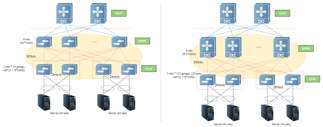
▲Figure 1: two-level network architecture topology diagram
In the above Figure 1, we analyze the 2 two-level network architecture topologies in terms of single/dual uplink mode, scale, equipment selection, and convergence ratio of the server as follows:
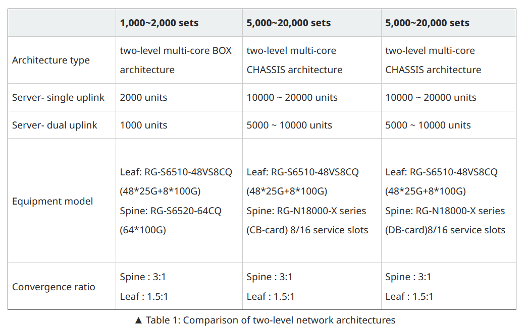
▲ Table 1: Comparison of two-level network architectures
When the scale of a single cluster server ranges from 1,000 to 2,000, a box-type (BOX) multi-core two-level architecture can be utilized to fulfill the demand. This architecture employs the same series of single-chip switch solutions for PFC (Priority-based Flow Control), + ECN (Explicit Congestion Notification), + MMU (Memory Management Unit) management. The chip waterline settings are highly consistent and well-coordinated. Additionally, the forwarding delay is low and the throughput is high. The entire network can implement RDMA services and network visualization solutions.
For a scale of 5,000 to 20,000 single cluster servers, a Chassis-based multi-core two-level architecture can be employed. The Spine layer core devices of this architecture offer two types of core boards to choose from:
1.CB-type boards cater to business scenarios with frequent many-to-one services and effectively reduce packet loss in such scenarios through a large cache mechanism.
2. DB-type boards are suitable for business scenarios with high requirements for RDMA networking and network visualization. This architecture also inherits the advantages of the BOX multi-core two-level architecture.
In the two-level networking architecture, the choice of architecture depends on the scale of single cluster servers and business needs. In the routing protocol part of the networking, EBGP (External Border Gateway Protocol) can be used between Spine and Leaf. All Leaf devices are deployed with the same AS number (Autonomous System number). The Spine layer replaces the AS number after receiving the Leaf layer route to resolve the EBGP horizontal split problem. When the business requires dual uplink of servers, it is recommended to use the de-stacking solution for Leaf layer deployment. "For details, see [Article 1] How to "de-stack" data centre network architecture.
see more : https://www.ruijienetworks.com/support/tech-gallery/internet-data-center-network-25g-network-architecture-design
© Affaires Officielles